Rankine cycle is named after Scottish engineer William Rankine, who analyzed an ideal heat engine with a condenser in 1859.
Rankine Cycle Process
Work Done and Efficiency
Temperature-Enthalpy (TS) Diagram
Schematics
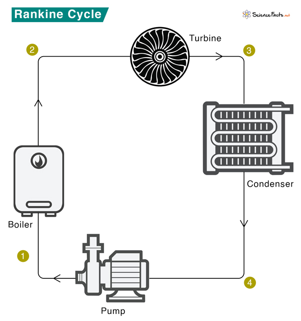
The schematic of a Rankine cycle is shown below. The Rankine cycle system comprises a pump, boiler, turbine, and condenser. The pump delivers liquid water to the boiler (1), which converts water to superheated steam. The steam drives the turbine that powers an electric generator (not shown) (2). It then leaves the turbine, cools down, and condenses to a liquid state in the condenser (3). Finally, the condensed liquid is pressurized by the pump (4) and sent back to the boiler (1). Step 1: Isentropic Compression The pump pressurizes liquid water from the condenser before it enters the boiler. The work done by the pump to compress water (Wpump) can be estimated from the enthalpy (H) change of water before entering (H1) and after leaving (H2) the pump. Wpump = H2 – H1 We assume an ideal scenario where no heat is lost to the surroundings during this step. Also, the pump requires little input energy, which is negligible for thermodynamic calculations. Step 2: Isobaric Heat Transfer Pressurized liquid water enters the boiler and boils until it forms superheated steam. The amount of heat (Qin) entering the boiler is equal to the enthalpy difference between superheated steam (H3) and liquid water (H2). Qin = H3 – H2 The heat, Qin, is supplied to the boiler by fuel. The pressure inside the boiler does not change during this step, so no work is done. Step 3: Isentropic Expansion At a high temperature and pressure, dry superheated steam from the boiler expands through the turbine, resulting in work. Pressure and temperature are reduced, and the steam is discharged to the condenser. The magnitude of the work done (Wturbine) is simply the negative change in enthalpy. Wturbine = -(H4 – H3) = H3 – H4 Again, we assume that there is no heat exchange with the surroundings. Step 4: Isobaric Heat Rejection It is the last step in the Rankine cycle. Wet steam from the turbine condenses into liquid water. Heat is given out during this process, which is equal to Qout = H4 – H1 Let us not calculate the heat absorbed (Qtotal) and the net work done (Wout) during one cycle. Qtotal = Qin – Qout Wout = Wturbine – Wpump From the first law of thermodynamics Qin – Qout = Wturbine – Wpump => Wout = Qin – Qout The thermal efficiency (η) of the Rankine cycle is The above formula for efficiency is derived under the assumption that there is no heat loss in the system. However, in a real Rankine cycle, each stage is associated with irreversible processes like friction, resulting in heat loss. Therefore, real Rankine cycle efficiency is far lower than the ideal. In a real Rankine cycle, this scenario does not happen. The compression by the pump and the expansion in the turbine are not isentropic, which means that these processes are not reversible, resulting in an entropy increase. Ultimately, the power generated by the turbine is reduced. The critical issue here is the formation of water droplets in the turbine, which leads to the deterioration of the turbine and a decrease in the engine’s overall efficiency. The practical way of overcoming this problem is by superheating the steam, represented by the DE portion of the diagram. Point D is at the border of the dual-phase region of steam and water. So, after expansion, the steam will be very wet. Superheating moves point D to the right and up to point E in the diagram. Therefore, the expansion will result in drier steam. This process is also called reheating the Rankine cycle.

