Otto cycle is named after German engineer Nikolas Otto, the first to build a working four-stroke engine in 1876.
Process
Efficiency
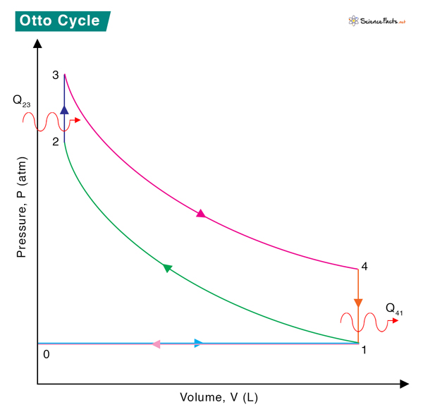
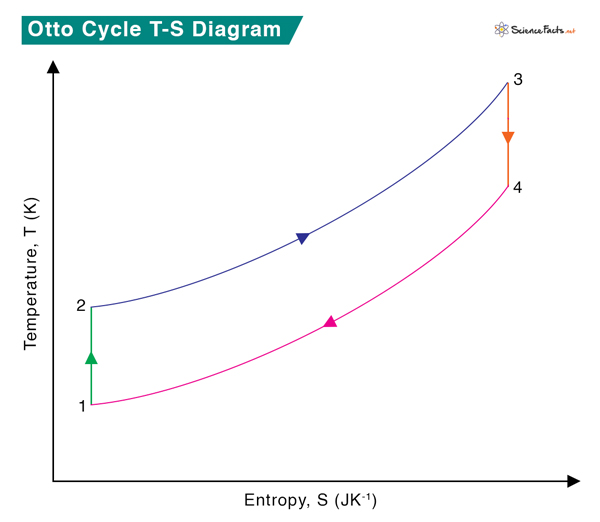
0 → 1 Intake stroke: Air-gas mixture is drawn into the engine at constant pressure. 1 → 2 Compression stroke: Adiabatic (isentropic) compression of the gas, resulting in increased temperature and pressure. 2 → 3 Combustion: Heat transfer from an external source to the mixture at constant volume resulting in the ignition—temperature and pressure increase. 3 → 4 Power stroke: Adiabatic (isentropic) expansion of the gas, resulting in decreased temperature and pressure. 4 → 1 Constant volume process during which heat is rejected by the gas, resulting in decreased temperature and pressure. 1 → 0 Exhaust stroke: Piston pushes the combusted gas out of the cylinder into the atmosphere at constant pressure. The TS diagram of the Otto cycle is shown below. During one complete cycle, the following processes occur:
The piston does work, W12, on the gas between stages 1 and 2, raising the temperature from T1 to T2.An external source transfers heat, Q23, to the gas between stages 2 and 3, raising the temperature from T2 to T3.The gas does work, W34, on the piston between stages 3 and 4, lowering its temperature from T3 to T4.The gas rejects heat, Q41, to the atmosphere between stages 4 and 1, lowering its temperature from T4 to T1.
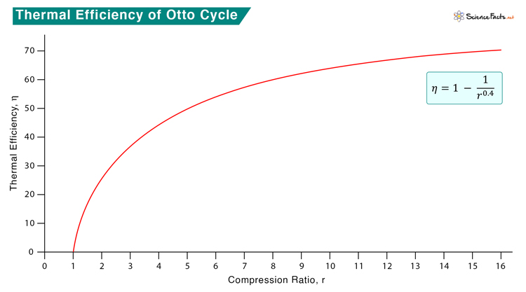
No work is done during the two isochoric processes, 2-3 and 4-1. The gas (system) returns to its original pressure, volume, and temperature at the end of the cycle. Therefore, the net change in energy of the system is zero. As a result, the energy (heat or work), Ein, entering the system must be equal to energy (heat or work), Eout, leaving it. Also, the convention is that energy entering the system is positive, and the energy leaving the system is negative. According to the first law of thermodynamics, energy cannot be completely converted into work. A part of the heat supplied to the system is converted into work, and the rest is rejected as heat. Therefore, Q23 = W34 + Q41 => W34 = Q23 – Q41 Then, we can write the expression for thermal efficiency as The heat absorbed and released by the gas during processes 1-2 and 4-1 are Where CV is the specific heat at constant volume. Therefore, We use adiabatic gas equations for the processes 1-2 and 3-4. Therefore, The ratio ( \frac{V_1}{V_2} ) is called the compression ratio and is denoted by r. For an air-gas mixture, γ = 1.4. Therefore, As the compression ratio increase, the efficiency also increases. However, the temperature will also increase. There is a chance that the air-gas mixture will ignite without a spark at high compression. It is in contrast to the Diesel cycle, where only air is compressed to a high ratio, and there is no risk of fuel auto-ignition.


